
Kathryn Porter, Watt-Logic
With the Feast of All Hallows rapidly approaching I thought it would be apt to explain how the grid is haunted by a concept that doesn’t really exist. A pre-occupation with a made-up concept risks the security of our power grids. In this blog I will explain how “vars” aren’t real, and treating them as if they are is creating existential risks on our power grids.
The reactive power beer anology
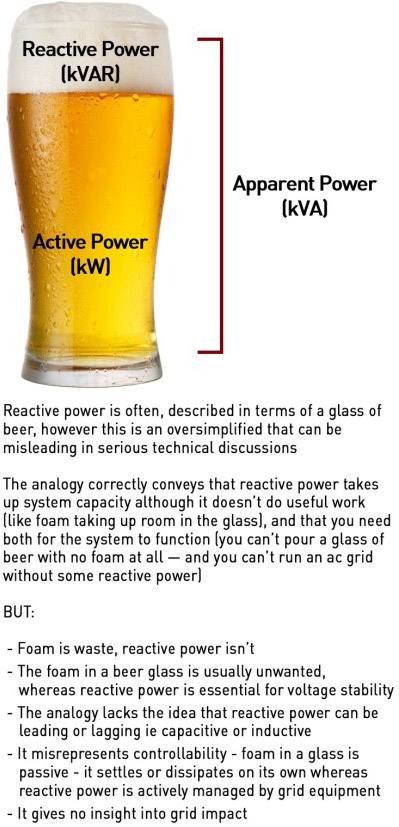
Not being able to properly explain reactive power is common in the energy industry – ask a dozen people to explain it and you’ll get twelve different answers. Most will reach for the beer-glass analogy where real power as the liquid and reactive power is the froth, or mutter something about “energy sloshing back and forth” on the grid. More sophisticated responses will mention capacitors “injecting vars” and inductors absorbing them. These phrases are repeated so often that they’ve become folklore. Unfortunately none of them describes what actually happens in power grids.
“Vars” in particular is an accounting fictions that obscure the underlying physics. And because we’ve replaced understanding of the physics with shorthand, we now incorrectly believe that anything producing current including batteries, solar inverters, or a clever algorithm, can perform the same stabilising role as the electromagnetic machines that built our power system. This misunderstanding could one day cost us the grid.
The volt-ampere was invented as a bookkeeping convenience in the 19th century – a way of quantifying energy oscillations between electric and magnetic fields in an alternating current system. It was never a physical thing, it was simply a way to balance equations. Over time, the mathematics replaced the meaning, and “supplying vars” became a commodity transaction rather than a description of an energy exchange.
To understand why this is a problem we need to get back to the basic physics. In this blog I am going to go back to absolute first principles and real physical things you could hold in your hand, to explain how our power grids really work and why failing to keep this front and centre means we may run headlong into trouble.
When the fields awaken: what exactly happens when voltage and current alternate?
Alternating current is created by the continual interaction between electric and magnetic fields. Inside every generator, a magnet (the rotor) spins inside coils of wire that form the stator. As the rotor’s magnetic field sweeps past the copper windings, it cuts through them, and according to Faraday’s Law of Induction, that changing magnetic flux produces an electric field in the wire. The electric field pushes electrons along the conductor, creating current. That current in turn generates its own magnetic field, so from the very first instant of generation, the electric and magnetic fields are bound together.
This mutual relationship of changing magnetic fields creating electric fields, and changing electric fields creating magnetic fields is exactly what Maxwell’s equations describe. A generator simply keeps those two fields interacting with each other in a perfectly timed loop – the magnetic field induces voltage, voltage drives current, and current sustains the magnetic field.
Voltage is the driver of current and should be considered more fundamental – a voltage differential creates an electrical potential difference analogous to gravitational potential at the top of a hill, which drives current flow (my GCSE and A-level physics teacher, who also looked exactly like Richard O’Brien of Rocky Horror Show and Crystal Maze fame taught it this way and it stuck). In this way, voltage is the manifestation of the electric field: an electric field creates electrical potential energy (voltage) which drives current.
In alternating current, the electric and magnetic fields complete fifty full oscillations each second, meaning the direction of current actually reverses a hundred times every second, tracing the familiar sinusoidal wave of voltage and current. It’s this physical coupling between the electric and magnetic fields and not any notional “real” or “reactive” power that underpins the entire behaviour of the grid.
In an alternating-current system made up of synchronous machines, energy is continuously traded between two reservoirs: electric-field energy, stored in capacitances, proportional to ½ C V², and magnetic-field energy, stored in inductances, proportional to ½ L I².
As voltage rises, electric-field energy increases, while as current rises, magnetic-field energy increases. In each half-cycle of the voltage / current waveform, these stores exchange energy: what one releases, the other absorbs. This is the phenomenon people loosely refer to as “reactive power”. However it has no separate fundamental existence and cannot be “injected” or “consumed”. It is simply a reflection of how the system’s electric and magnetic energies interact.

What actually happens as voltage changes? Take a sine-wave voltage, assuming the grid is already energised and we’re taking a random snapshot (when the grid is first energised the behaviours are somewhat different as there is initially no load) starting at t=0 – voltage is zero and rising positive. Current and voltage are almost in phase (if they are perfectly in phase there is no active power, which is an abstraction too far!)
At this point, the electric fields of capacitors are already charged, and they begin to release energy into the circuit. Inductors, whose magnetic fields are empty, begin to absorb this energy as current builds. A quarter-cycle later, voltage reaches its peak. The inductors’ magnetic field are full and the capacitors’ electric fields are empty. As voltage falls, the inductors release their stored magnetic energy and the capacitors rebuilds their electric fields. This rhythmic exchange continue indefinitely.
Again, this is an abstraction. In the context of a synchronous generator connected to the grid, the “inductors” and “capacitors” are not separate components, they are distributed physical properties of the generator and the power system around it.
Generators are inherently inductive and its magnetic system dominates. Its coils, iron core, and the air gap between rotor and stator all store energy magnetically. The capacitance between conductors (turn-to-turn, phase-to-phase, and to ground) is tiny – it exists, but it’s orders of magnitude smaller than the inductive effects. In isolation, the generator behaves almost entirely like an inductor, and when it is connected to a resistive or capacitive load, current lags voltage because most of the energy is cycling in and out of the magnetic field, not the electric one. This is also why we say the generator’s power factor is lagging by nature – it doesn’t provide equal electric and magnetic energy exchange within itself.
To get a balanced exchange of energy between electric and magnetic fields, the inductive generator needs to be connected to a capacitor. Fortunately the power grid itself is capacitive in nature. Transmission lines, cables, transformers, and loads contribute distributed capacitance across the system. In steady operation, the generator’s inductive energy storage and the grid’s capacitive energy storage form the complementary halves of the ac oscillation.
When voltage and current are nearly in phase, as on a healthy grid, the electric and magnetic fields remain closely balanced and voltage is steady. At the theoretical extremes, 90o out of phase, the timing reverses, and the roles of capacitor and inductor swap. That is capacitors charge and inductors discharge when voltage rises and vice versa. (Most textbooks use the 90o out of phase scenario as the base case so will state that capacitors charge and inductors discharge when voltage rises, but this is not typically what we see on power grids where current and voltage are almost perfectly in phase.)
In addition, in the near-in-phase, power-delivering case typical of power grids, the capacitor is not just storing and releasing reactively, it’s participating in the transfer of real energy through the circuit. At t=0 V=0, current is flowing into the load and the system is delivering real power. The magnetic field in the inductive parts (coils, lines) is growing, ie inductors are charging. The capacitor’s voltage is near zero, but its “plates” (eg the power line and the ground) already hold charge from the previous cycle.
As voltage rises, current is still flowing in roughly the same direction, so the capacitor’s upper plate loses charge (it discharges) helping to drive current forward and support the voltage rise. The inductor simultaneously absorbs more current and stores magnetic energy.
The balance of shadows and light: what “voltage support” really means
In a stable grid where current and voltage are almost in phase, when voltage increases, current increases and the electric field falls as capacitances discharge. Magnetic fields rise as inductances charge. The relationship between supply and demand interacts with these relationships: as demand increases, the current drawn rises so electric energy falls and magnetic energy rises.
As energy is drawn from capacitances to meet the additional load, this energy is converted to active power (a grid engineer would say the reactive power falls). Now the magnetic fields in the circuit dominate. This manifests as both a phase shift between voltage and current, and a reduction in peak voltage amplitude. Because magnetic energy now dominates, the system behaves more inductively. This means current begins to lag voltage – it takes a little longer for the current to reach its peak because more of the energy is cycling through magnetic fields.
The reduction in the energy stored in the electric-field also means the outright magnitude of voltage drops ie not just as part of the alternating cycle. Any reduction in electric field strength translates directly to a drop in line voltage. This is why, in simple terms, when a big load is turned on, lights dim momentarily – not only phase but also the absolute potential difference falls because charge is being drained from the distributed capacitances.
A synchronous generator senses this in two ways: mechanical drag where the shaft slows fractionally because electrical torque has increased (frequency effect), and electrical field weakening as the terminal voltage falls because system capacitances have discharged. The automatic voltage regulator in the excitation system detects the voltage fall and immediately increases excitation current in the rotor field. This strengthens the generator’s internal magnetic field, pushing more electric-field energy (voltage) into the system, replacing what was drained, and restoring both the phase angle and peak voltage level to their previous state.
At the same time, the mechanical governor increases torque to restore frequency, closing the loop on both axes – voltage stability via excitation, frequency stability via torque.
The same magnetic energy that stabilises voltage also provides short-circuit strength – if voltage collapses locally, the collapsing field drives a surge of current that resists the change, anchoring the waveform. This natural elasticity is what makes a synchronous machine a stabilising presence.
The shift from field language to “vars” detached operators from physical reality. Once reactive power was treated as a tradable commodity, it became tempting to assume that any current-producing device could deliver it – if the grid code asks for a certain “var capability,” a battery inverter can be programmed to meet the number, so why not use it instead of a generator?
Because the physics isn’t the same. A generator alters magnetic flux, while an inverter simply alters a control angle in software. The first releases or absorbs real field energy; the second merely recalculates its current vector – inverters have no magnetic component to play with. That distinction doesn’t matter when nothing is wrong, but it matters a lot when the grid is disturbed.
The silent gatekeepers: how inverters actually work
Now we understand what synchronous generators are, we should do the same with inverters. When people talk about “power electronics,” they often picture racks of mysterious black boxes. But inside those boxes are simple transistor – tiny pieces of doped crystal acting as controllable valves for electrons. Every inverter on the grid, whether in a home battery or a 400 MW converter station, is nothing more than thousands of these valves turning on and off in carefully timed patterns.
These devices start with the raw material which is silicon. Silicon is a natural insulator (ie does not conduct electricity). Each silicon atom shares its four outer electrons with four neighbours, forming a rigid crystal lattice with no free electrons to move, which is why it is electrically inert – it can hold charge, but the absence of free electrons means current cannot flow.
To make silicon useful in power electronics, tiny quantities of other elements are introduced in a process known as “doping”. This involves adding a few atoms per million to subtly change the crystal’s electrical characteristics. Phosphorus or arsenic have five outer electrons instead of four – when added to silicon, each dopant atom has one spare electron not needed for bonding. This electron can move freely through the crystal, allowing it to conduct electricity. The result is n-type silicon, rich in mobile negative charge carriers.
Boron or gallium, by contrast, have only three outer electrons, leaving one missing bond – a “hole” that behaves like a positive charge carrier moving in the opposite direction. That creates p-type silicon. When n-type and p-type regions are placed next to each other, electrons and holes diffuse across the boundary and recombine, leaving behind charged atoms that form an internal electric field known as the depletion region. This junction conducts easily in one direction but resists current in the other and is s the principle of a diode, the building block of all transistor behaviour. A transistor adds a third terminal that controls this internal field.
In modern power devices that control terminal is the gate, separated from the silicon by a wafer-thin insulating oxide. When a small voltage is applied to the gate, it pulls charge carriers into a channel beneath it, linking two main terminals (the source and drain) so that current can flow. Remove the gate voltage and the channel collapses, blocking the path again.
It’s easiest to imagine the transistor as a drawbridge for electrons: the gate voltage lowers the bridge, allowing charge to cross; remove it, and the bridge rises, cutting the path. There are no moving parts, just electric fields shaping the flow of electrons within a crystal only microns thick.
Each power transistor chip is a small square of silicon or silicon carbide mounted on copper for heat removal. It’s bonded to metal leads and sealed in a ceramic case, about the size of a coin or postage stamp. If you pick one up, it feels cool and inert, but inside it’s capable of switching hundreds of amps and blocking thousands of volts. An industrial inverter or grid converter contains hundreds of these modules, clamped onto water-cooled plates to remove the heat produced every time they switch.

Six transistors are arranged in three pairs, one for each phase of the output. Each pair acts like an electronic switch, alternately connecting that phase to the positive or negative side of the inverter’s internal dc supply. A digital controller switches them on and off tens of thousands of times per second using pulse-width modulation. By varying how long each transistor stays on or off, the controller makes the average output voltage follow a sine wave.
A simple L–C filter smooths out the pulses, and the result is clean alternating current ready for the grid. (An L-C filter consists of a combination of inductors (L) and capacitors (C) to cut or pass specific frequency bands of an electric signal. Capacitors block dc currents but pass ac more easily at higher frequencies. Conversely, inductors pass dc currents as they are, but pass ac less easily at higher frequencies. As capacitors and inductors are passive components with opposite properties combinations of them can reduce noise in electrical signals.)
When a waveform is displayed on a scope trace, what is actually visible is the collective behaviour of hundreds of tiny crystals, each opening and closing in nanoseconds under software control.
This sounds wonderful but there are hard physical limits inside the silicon. Each transistor has strict physical boundaries defined by materials science:
- Voltage limit: set by how strong an electric field the crystal can withstand before it breaks down and conducts uncontrollably
- Current limit: defined by how much heat can be drawn away before the silicon melts or the wire bonds fuse
- Switching speed: governed by how quickly electrons can move in and out of the conduction channel without causing localised charge buildup and failure
The combination of these constraints defines the safe operating area and is designated by a triangular patch on every transistor datasheet. Beyond these limits and the device will fail, usually instantaneously and irreversibly. This is why inverters have hard current ceilings, intricate cooling, and multi-layered protection circuits.
At any moment, the inverter’s total output current is limited by the sum of the currents through its transistors. That total current must cover both the part delivering real power and the part maintaining the grid’s electric-magnetic balance (the “field” component):

If the grid voltage dips and the inverter has to increase its “field” component to help restore electric energy – it can only do this by reducing its real-power output. Unlike a synchronous generator which can exchange energy between its magnetic and electric fields without affecting mechanical torque, the inverter has only one resource: current. Every ampere of current devoted to supporting voltage is an ampere no longer delivering energy to the grid.
The dangerous illusion of vars
The key difference between an inverter-based generator and a synchronous generator is that the latter stores energy in its magnetic field and can exchange it dynamically with the grid. A transistor stores nothing, and has no magnetic field. Even though wind turbines do posses magnetic properties, they are not synchronised to the grid (because they cannot rotate at a stable speed), and the very existence of the inverter interfacing with the grid means this magnetic resource cannot be used for grid support. And even if a device that could access this resource could be developed, it wouldn’t be very useful since wind turbines tend to be located in remote areas and voltage support needs to be local: supporting voltage in the middle of the North Sea isn’t all that helpful for the gird as a whole.
So inverter-based generators can release charge from a capacitor or control current through an inductor, but they have no internal electromagnetic inertia. So when voltage or frequency changes faster than its control loop can respond, they cannot “push back” naturally. The inverters just saturate and drop out.
Grids that were once stabilised by tonnes of metal, are increasingly governed by milligrams of doped silicon. Their operation is precise, efficient, and in many ways, astonishing, but they have no physical “spring”. When engineers say an inverter is “supplying reactive power,” nothing mystical is happening – the inverter isn’t injecting invisible “vars” into the grid, it’s simply redirecting a portion of its finite transistor current away from delivering real energy and towards supporting the grid’s electric field.
Inside the silicon, the control system tilts the current vector so that part of the transistor’s current now flows out of phase with the voltage. Mathematically, that looks like “reactive power” concept that describes the exchange of energy between the electric and magnetic fields of synchronous generators. But physically, it’s just the controller commanding the electron valves to momentarily spend more of their available current helping the electric field rather than the mechanical load. Because total current is capped by the transistor’s material limits, this trade-off is absolute. There is no separate pool of “reactive power” ie energy stored in the magnetic fields of inductive devices including synchronous generators, only a redistribution of current within tight atomic constraints.
Frequency reflects the balance of active power: generation versus demand. When inverters divert current from real power to field control, total active generation falls. If thousands of units respond identically to a voltage dip, as most are programmed to do, the system’s real power output will collapse even as voltage recovers. The immediate consequence is a frequency drop.
A control philosophy that treats voltage and frequency as independent channels suddenly discovers that they are not: both draw on the same finite current vector. In fact, we can borrow from a finance concept here: “dynamic conditional correlation” describes the way in which normally uncorrelated assets can become correlated under market stress. During the 2008 financial crisis a need for liquidity drove banks to sell assets of all types chasing cash, meaning that assets whose values were normally uncorrelated, all lost value at the same time due to the selling pressure.
Similarly, a voltage response relying on inverters diverting current from active power to voltage support will cause a frequency drop in a way that is simply impossible in a grid based on synchronous generators which separate these roles naturally – torque governs frequency, excitation governs voltage – but converters cannot.
This risk is baked in to our grids. Modern grid codes require all inverters to follow near-identical “volt–watt” and “volt–var” curves. When a regional voltage sag occurs, every device interprets it the same way and responds in the same way at the same time. Their combined action releases electric-field energy but simultaneously strips the grid of active power. What begins as a mild voltage disturbance becomes a coordinated frequency collapse. No one planned this but it’s a by-product of abstraction. Designers thought in terms of reactive power numbers rather than field energy and never noticed that the two controls are drawing on the same resource.
So when people assert, as they have done in relation to the current voltage control issues in Spain, that batteries and grid-forming power electronics can replace conventional synchronous generators, providing both traditional inertia and voltage support, they are not only wrong, they risk turning a small fault into a massive grid failure.
Exorcising the grid
A synchronous generator’s magnetic and mechanical systems are physically decoupled. It can transfer energy between its rotor field and the grid’s electric field without touching the mechanical torque that defines its active power. This separation is what makes synchronous generation intrinsically stable: voltage control doesn’t interfere with frequency control. It’s also what gives the grid its electromagnetic “stiffness” – the ability to resist both voltage and frequency perturbations simultaneously. Remove that separation and the grid becomes brittle.
Once inverters dominate, voltage and frequency cease to be independent dimensions, they merge into a single fragile dynamic limited by semiconductor current and software timing.
The entire modern stability philosophy is based on separate voltage and frequency control loops, and separate service markets for “reactive” and “active” power. But in an IBR dominated grid that is no longer true.
Imagine a sunny afternoon, low demand, high renewable output. A transmission fault causes a brief voltage dip. Every inverter in the region responds within milliseconds, releasing electric-field energy and cutting active power. Frequency falls, so other controls react, but they’re already at their current limits. Protection relays trip, and the disturbance cascades. The system fails because its components all did exactly what the “var” abstraction told them to do.
System operators need to get back to the physics and remember that “reactive power” is not a product – it’s not even real in the way they think it is. It’s not a “thing” that can be injected into or absorbed from the grid; it is simply the visible trace of the continuous exchange of energy between electric and magnetic fields. Understanding that exchange – how capacitances and inductances behave as voltage and current evolve – is essential to keeping the grid stable.
Synchronous generators manage it naturally, and for free, but inverters can only imitate it within narrow limits, and at a cost (haircutting active power output, ie selling less electricity to consumers). Designing a secure power system requires recognising that limitation and maintaining enough true electromagnetic machinery to anchor the fields of the network. Until we do, we’ll continue to model our grid in made-up units, unaware that the physical system underneath speaks an entirely different language.
Original article l KeyFacts Energy Industry Directory: Watt-Logic