WORKING WITH 4D SEISMIC AND INVERSION
Introduction
Rock physics has its origins in the 1980s with the evolution of seismic processing flows able to retain true, geologically meaningful amplitudes. Since that time, rock physics modelling (when correctly applied) has been used to de-risk amplitude driven hydrocarbon prospects around the world. Many workers are now bringing rock physics methods to CCS challenges, but what questions can it answer and what limitations do we need to be aware of?
In the CCS domain, there are three main workflows where rock physics can add value:
- Rock Characterisation.
- Working with 4D Seismic and Inversion.
- Seismic Modelling, specifically fluid substitution modelling.
This article will focus on what the change in pore fluid composition (from brine to various saturations of CO2) looks like on time-lapse seismic and how this can be exploited by seismic inversion. After rock characterisation, seismic modelling would normally be the next step to assess the feasibility of 4D seismic and inversion products, however, I think it’s important to illustrate the outputs of rock physics modelling before getting into the details (and pitfalls) of how those models are applied.
4D SEISMIC
Movement of injected CO2 within the subsurface must be monitored in order to demonstrate that containment is successful, and that the plume is behaving as predicted by the reservoir models (conformance). 4D seismic can provide an invaluable tool to visualise movement of a CO2 plume through time. Figure 1 below shows some of the 4D seismic images from Sleipner which beautifully visualise the migration of CO2. However, it cannot be assumed that 4D seismic for CO2 monitoring will be universally successful: Rock properties in some areas are simply not conducive to highlighting changes in fluid fill through seismic imaging. Fortunately, rock physics modelling can be used ensure that 4D seismic is only acquired in places where it can add value (more on feasibility modelling in the next article).
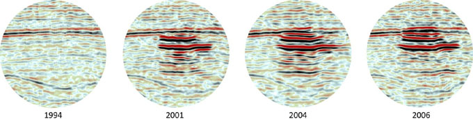
Figure 1. Four vintages of time-lapse seismic showing the Sleipner CO2 plume.
Sleipner 4D Seismic Dataset provided by the Sleipner Group on the CO2 DataShare. Data Owners: Equinor, PGNiG & Orlen.
License: CO2DataShare.
SEISMIC INVERSION
The Essentials of Rock Physics course (now available through Merlin) dedicates a full day to seismic inversion. I cannot hope to distil everything here, nevertheless, I will start by setting the scene…
Rather than looking at reflectivity seismic (which represents geology as a series of interfaces), we can invert the seismic instead to layer-bound rock properties known as impedances. These impedances can then be related to geologically meaningful parameters such as porosity or saturation, allowing a 3D cube representing the desired property to be generated. With any inversion project, it is critical to remember that seismic inversion is a non-trivial problem which provides non-unique geological solutions.
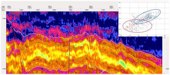
Figure 2. Seismic inversion revealing different lithological units.
In recent years, various contractors have made significant advances on classical trace inversion, and the assumptions made by modern software packages are becoming much more geologically reasonable. Regardless of the algorithm selected for seismic inversion, the first step should always be a feasibility study to ensure the local rock properties are conducive to seismically imaging the property you are interested in (e.g. CO2 saturation). If the answer is no, an alternative monitoring technology must be sought.
THE SEISMIC RESPONSE TO CO2 INJECTION
Injecting CO2 into a clean, porous, brine bearing reservoir will affect both the mix of fluids present, and the pressure in the storage unit. The changes to elastic properties as a result of these two factors are summarised in Table 1 below, with the final row listing the factors which influence the magnitude of the saturation or pressure effect.
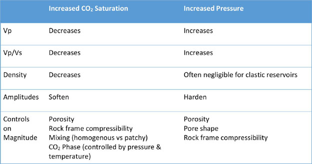
Table 1. Summary of the impact of CO2 injection on elastic properties of a porous, brine-bearing reservoir.
If the geology is favourable, we can qualitatively estimate saturation and pressure changes by examining amplitude and AVO changes on time-lapse seismic. Although saturation and pressure act in opposing “directions”, it can be challenging to decouple their relative contributions from a seismic amplitude, especially if you lack shear sonic calibration data. For clastic reservoirs, models suggest that the seismic response to increasing CO2 saturation commonly dwarfs that attributable to pressure changes. However, with so few published examples of real-world data, I would keep an open mind regarding the influence of pressure on seismic amplitudes.
The summary in Table 1 holds for CO2 storage in depleted oil or gas fields because CO2 is acoustically “softer” than most hydrocarbons. The exception to this is lighter gases such as methane or ethane. CO2 is denser than these gases, so increasing the CO2 saturation of a depleted methane or ethane field would cause seismic amplitudes to become slightly “harder”. Unless the seismic has excellent signal, this response is likely to be more difficult to discern from 4D amplitude changes.
In the case of carbonate storage units, Table 1 is still valid, but the rock frame will probably be stiffer. This means seismic amplitudes are likely to be less susceptible to changes in fluid fill i.e. when CO2 saturations are introduced. Carbonate storage units may also be impacted by reactions with carbonic acid created when CO2 dissolves in brine.
ONWARDS TO SEISMIC INVERSION
Assuming the rock properties are favourable for producing a visible amplitude change after the injection of CO2, seismic inversion provides a useful method of relating seismic amplitudes to CO2 saturations and/or pressure increase.
You can use your favourite flavour of seismic inversion to produce saturation and pressure cubes from the base and monitor seismic surveys (with associated uncertainties). By comparing the results, you should be able to track where the CO2 plume has migrated, and perhaps be able to see where pressure changes are focused. If the seismic data are good enough, you may even be able to use the inversion cubes to give a quantitative understanding of saturation and pressure changes through time. These results can be used to confirm successful containment and verify (or update) the reservoir model and injection plan.
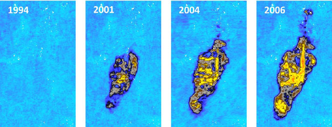
Figure 3. Windowed amplitude extraction from four vintages of time-lapse seismic covering the Sleipner CO2 plume.
Sleipner 4D Seismic Dataset provided by the Sleipner Group on the CO2 DataShare. Data Owners: Equinor, PGNiG & Orlen.
License: CO2DataShare.
CONCLUSION
Acquisition of repeat (4D) seismic surveys can be used to evaluate amplitude and AVO changes caused by injecting CO2 into a storage unit. This provides a qualitative measure of where the CO2 plume has migrated in the subsurface. Seismic inversion can then be carried out on both the base and monitor surveys to produce cubes representing pressure and/or CO2 saturation, allowing comparisons to be made between pre-injection and the next time-step. Assuming the data is good enough, the inversion results can be used quantitatively to verify or update the reservoir model and injection plan.
Although the general elastic response to CO2 introduction is laid out in Table 1, every storage complex is different and will require local feasibility and calibration studies. In some cases, a rock physics feasibility study may reveal that the storage complex is not likely to produce a visible seismic anomaly upon the injection of CO2. In these cases, acquiring (and inverting) monitor surveys would be a waste of resources and an alternative technology will be required to monitor the CO2 plume.
Next time…
In my next article I’ll describe the modelling workflows required for assessing whether there’s likely to be a 4D amplitude response (feasibility stage) and calibrating what that response is (monitoring stage). There are several significant differences between working with CO2 and hydrocarbons, so make sure to read my next article to learn how to avoid these pitfalls.

Eleanor Oldham, Senior Geophysicist at Merlin Energy Resources
KeyFacts Energy Industry Directory: Merlin Energy Resources